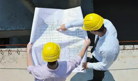
During the analysis, mechanical drawings in construction projects are of high priority. It helps stakeholders to communicate the ideas of the designers and the clients. Specifically, during the mechanical construction process, these drawings are focused on moving on with the mechanical work. Other than mechanical drawings, the electrical, architectural, finishing, structural, and plumbing drawings are also a part of the process.
However, the main purpose of these drawings is to give an idea of the layout. It shows the inside and outside of the building and how it may look. Most importantly, the professionals extract the pinpoint measurements to prevent under- or over-ordering of materials. Stick with this article to learn about the insights of mechanical construction projects!
DIG IN TO GET ANSWERS FOR HOW MECHANICAL DRAWINGS ARE USED IN CONSTRUCTION DOCUMENTATION TO PREVENT MISTAKES IN THE FUTURE!
Mechanical Drawings: Explanation
Mechanical drawings include technicalities that showcase the details of the building’s heating, ventilation, air conditioning, and transportation systems. As, mechanical part of the building is complex, it requires attention to every small detail.
These drawings are created by the architect and show what their plans are according to the client’s preferences. Moreover, drawings have to be comprehensive and cover all the details. They are based on the client’s floor and ceiling structural plans.
The following are the components that are highlighted in the mechanical drawings:
- HVAC Systems
- Ductwork Layout
- Duct Sizes and Routes
- Air Handling Units (AHUs)
- Exhaust Systems
- Diffusers and Grilles
- Return and Supply Air Systems
- Mechanical Equipment Locations
- Chillers
- Boilers
- Pumps
- Piping Layout (Chilled Water, Hot Water)
- Pipe Sizes and Routes
- Valves
- Insulation Details
- Control Systems
- Thermostats
- Fire Dampers
- Smoke Dampers
- Mechanical Room Layouts
- Equipment Schedules
- Refrigerant Lines, etc.
What are the Types of Mechanical Drawings?
Manual Drawings
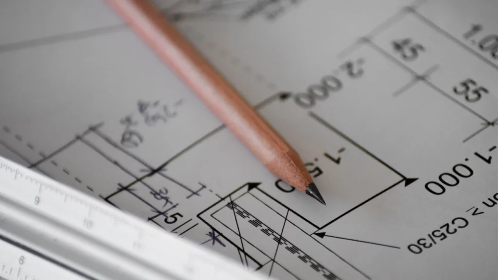
In traditional methods, manual mechanical drawings were used, which were hand-drawn using protractors, rulers, pencils, and sheets, as well as other tools. But these types of drawings were quite time-consuming and still prone to mistakes!
Computer-aided design (CAD)
CAD drawings are quite famous in the construction process because they include two-dimensional and three-dimensional drawings. If you are choosing Building Information Modeling (BIM), you will get 3D CAD, perfect for accurate measurements and cost estimations.
2D CAD
Two-dimensional CAD can create curves and straight lines to showcase accurate measurements. With the help of software, the process is simpler, and mistakes are easy to fix.
Why are drawings used in construction documentation?
Alone, mechanical drawings are not enough to make the space functional. Different types of drawings help form building systems, refine the design requirements, and reduce the chances of mistakes. However, it is divided into the following sets of drawings:
- Architectural drawings
- Structural drawings
- Electrical drawings
- Mechanical drawings
Moreover, these drawings are necessary for construction permits. So, it is required in the initial stage of the construction planning. Local authorities review these drawings to review them according to the location.
Applications of mechanical drawings in the construction industry
Any construction project is incomplete without mechanical drawings. These types of drawings are one of the most crucial to understanding the overall building structure. Specifically, construction estimators plan the project finances, amount of materials, labour hours, measurements, etc., through these drawings for mechanical work!
What Do Mechanical Drawings Include?
Other than the components that are discussed in the article, the following are the details included in mechanical drawings;
- Title blocks consist of data about the designer’s name, finish, material, description, general tolerances, part weight, etc.
- A bill of materials or the items required for the project.
- Break lines are inserted to showcase an unbroken view, which is important to keep things organized in the space.
- The next thing included in the mechanical architectural drawings is continuous lines that represent the physical boundaries of the items.
- The center lines showcase the geometrical view, which indicates slots, holes, and other features!
- Hidden lines are included in the drawings, which show those spaces that are not visible in a certain view.
- Labels to highlight the need for inspection and quality requirements.
IF YOU REQUIRE MECHANICAL PROJECT COST ESTIMATIONS, CONSULT OUR EXPERTS AND GET THE MOST AUTHENTIC AND REALISTIC OUTPUTS!
Conclusion
In short, mechanical drawings in construction projects play a major role in preventing mistakes and running out of pockets. However, the drawings need to be super accurate; otherwise, inaccuracy can lead to plenty of design mistakes. So, it is necessary to get professional help and make the communication process easier for stakeholders. This way, all the technical details are covered efficiently without worrying about design mistakes. Thus, accurate technical drawings are the need of the hour because they directly affect the project budget. A minor mistake in the drawing can affect the whole project budget. That is why it is recommended to seek professional help for your mechanical projects from the initial to the execution phase.